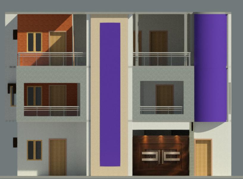
front external lift follow the reference model exactly position the lift externally at the centre of the front fa ade projecting forward from the existing building the lift shaft must follow the exact shape dimensions proportions positioning and architectural enclosure shown in the supplied lift model do not create a completely transparent full glass lift tower do not use continuous blue reflective glass on all four sides of the lift shaft construct the lift shaft with a clearly defined solid structural enclosure using rcc or appropriately finished structural wall surfaces as depicted in the reference model use glass only in the specific designated openings or glazed portions shown in the reference model maintain the solid side walls structural framing and enclosure arrangement as represented in the model apply a refined exterior finish to the lift shaft using the same colour palette as the main building with subtle charcoal or dark grey accents provide appropriate lift entrance openings at each floor extend the lift from ground level to the top floor garden level preserve the exact external projection and alignment shown in the model most important treat the supplied lift model as the controlling reference for the lift s physical construction and appearance do not reinterpret it as a panoramic glass lift all glass shaft or decorative glass tower only improve its material finishes and detailing without changing its actual geometry or enclosure design