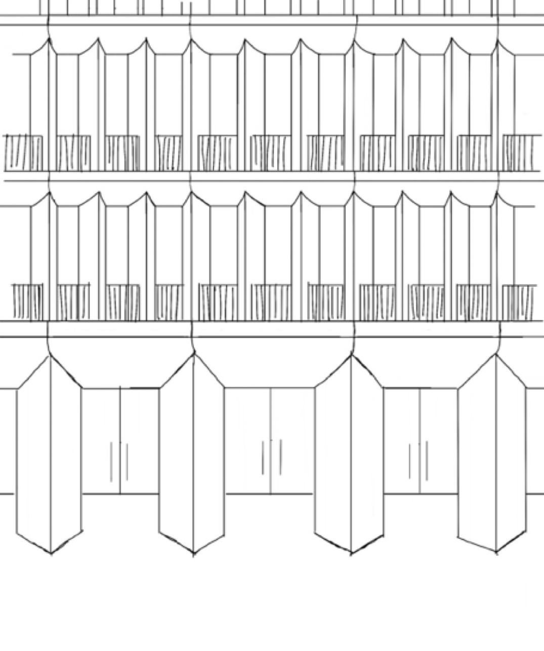
use the attached architectural sketch as the primary and authoritative reference for the geometry the objective is to translate the sketch into a clean precise 3d architectural fa ade study geometry only do not introduce materials landscape people furniture or environmental design at this stage the sketch defines fa ade composition proportions structural rhythm number and spacing of elements relationship between ground floor and upper levels window rhythm geometry of the projecting vertical elements geometry of the curved horizontal elements do not redesign or reinterpret the architecture camera and crop preserve the camera position and frontal composition represented by the sketch the drawing is not a complete building elevation it represents only a cropped zoomed in portion of a much larger building the building continues beyond left edge of the image right edge of the image top edge of the image the image boundaries are camera crop boundaries not building boundaries do not create building corners lateral terminations roof parapet termination complete symmetrical fa ade complete building composition architectural elements may naturally be cut by the left right and top edges of the image maintain a predominantly frontal architectural view with vertical lines perfectly vertical overall fa ade organization the fa ade consists of two clearly related but geometrically different systems 1 monumental ground floor columns 2 a finer repetitive system of vertical and horizontal elements on the upper levels the geometry of the ground floor and upper floors must follow the sketch accurately ground floor reproduce the ground floor geometry exactly according to the sketch the ground floor consists of large projecting columns positioned in front of recessed glazed entrances ground floor columns the ground floor columns have a square cross section each square column is rotated approximately 45 degrees in plan relative to the fa ade this creates the characteristic diamond like appearance in frontal view all ground floor columns must be identical in physical dimensions identical square cross section identical width identical depth identical height identical rotation identical projection from the fa ade do not vary the dimensions from one column to another the columns continue upward and connect geometrically with the fa ade zone above as represented in the sketch between the columns maintain the recessed glazed entrance openings shown in the drawing keep the entrance geometry simple and secondary to the main fa ade structure upper levels vertical elements the upper level vertical elements are not square columns they are rectangular elements rotated in plan this distinction is critical ground floor square section rotated approximately 45 degrees upper levels rectangular section rotated in plan because the upper elements are rectangular the two visible faces must have different widths create one single master rectangular vertical element and repeat it throughout the upper fa ade every standard upper vertical element must have exactly the same rectangular cross section the same width the same depth the same height the same projection the same proportions the same rotation angle for the standard orientation shown in the sketch left visible face narrower face right visible face wider face this relationship must remain identical throughout the repeated fa ade do not randomly rotate individual elements do not vary their width or depth do not create wider or thinner columns do not alternate their geometry unless specifically indicated by the sketch critical equal window bay widths the spacing of the upper vertical elements must be completely regular all window bays must have exactly the same width the original hand sketch may contain minor drawing inaccuracies where some windows appear slightly wider or narrower ignore these hand drawing inconsistencies interpret the design as a mathematically regular repetitive fa ade system the distance between consecutive upper vertical elements must therefore remain constant every window opening must have the same width every repeated bay must have the same dimensions the fa ade rhythm must read as identical vertical element identical window bay identical vertical element identical window bay identical vertical element upper levels horizontal elements this is one of the most important geometric characteristics of the design the horizontal elements are not conventional straight beams they are also not straight beams with small curved connections at their ends instead the entire horizontal element between two consecutive vertical elements forms one continuous very smooth and shallow curved surface the curvature extends across the full width of every window bay curvature geometry use the window opening as the geometric reference the lowest part of the horizontal curved element corresponds to the horizontal upper edge directly above the window from this horizontal edge above the window the surface gradually rises toward each adjacent projecting vertical element therefore the geometry across each bay is vertical element smooth gradual descending curvature lowest horizontal portion directly above the window smooth gradual ascending curvature next vertical element the curvature must be extremely smooth and continuous it should read as a gently tensioned or draped architectural surface between the projecting vertical elements there must be no identifiable short transition zone the whole horizontal element participates in the curvature critical curvature rule do not create a straight beam with curved ends a short concave transition a deep u shaped curve a semicircular arch a scalloped decorative fa ade an abrupt curve triangular connections angular connections steps kinks the curvature is shallow long and continuous it gradually develops throughout the entire width of the bay connection between horizontal and vertical elements the curved horizontal surface must connect naturally into the rotated rectangular vertical elements at these intersections the horizontal geometry follows and merges into the geometry of the vertical element the vertical element should appear to emerge naturally from the highest point of the curved horizontal surface there should be no abrupt junction or separate connecting piece the vertical and horizontal elements must read as one continuous sculpted fa ade system reversed orientation bay follow the specific variation visible in the original sketch most upper vertical elements follow the standard orientation left face thinner right face wider however there is one specific bay between the two major alignment lines on the left side of the composition where the orientation of the vertical elements is reversed in this specific location only rotate the same rectangular element in the opposite direction important this is not a different column type it uses exactly the same rectangular cross section dimensions depth and proportions only its rotational orientation changes the window bay width must remain exactly the same as every other bay do not widen or narrow the window because of this rotation after this local reversed condition continue the regular fa ade system according to the sketch upper windows place tall narrow glazed openings between the repeated vertical elements all window openings must have identical width have identical height within each level remain equally spaced sit behind the projecting fa ade structure the glazing must remain visually recessed relative to the vertical and horizontal fa ade elements balustrades maintain the balcony balustrade elements shown in the sketch they should follow the same repetitive window rhythm keep them geometrically simple thin and regular do not allow the balustrades to modify the width or spacing of the fa ade bays vertical alignment maintain the major vertical alignments established in the sketch the upper fa ade system must relate precisely to the larger structural rhythm of the ground floor do not randomly shift the upper fa ade grid preserve the intended alignment between the main ground floor elements and the upper fa ade composition geometry study only render the entire architectural model using a uniform matte white clay material use matte white for all solid architectural elements simple neutral grey transparent glazing no realistic material textures the purpose of this image is only to evaluate geometry proportions fa ade rhythm column dimensions rotation depth curvature alignment crop do not add no stone no brick no concrete texture no metal finishes no timber no colors no material joints no weathering no vegetation no trees no planters no people no furniture no cars no signage no street elements no surrounding buildings no decorative objects lighting use simple neutral soft daylight the lighting should clearly reveal the depth rotation and curvature of the fa ade without creating a dramatic atmosphere final priority the original sketch is the authority prioritize the following geometric rules 1 preserve the existing frontal camera and cropped building interpretation 2 ground floor columns are identical square sections rotated approximately 45 degrees 3 upper vertical elements are identical rectangular sections with one face visibly narrower than the other 4 create one master upper vertical element and repeat exactly the same dimensions throughout the fa ade 5 all upper window bays have exactly the same width and spacing 6 the upper horizontal elements have a continuous smooth shallow curvature throughout the full width of each bay 7 the curvature begins from the horizontal upper edge of the window and gradually rises toward the projecting vertical elements 8 the horizontal curved surfaces and vertical elements merge as one continuous architectural geometry 9 follow the specific reversed orientation indicated in the sketch without changing the dimensions of the element or the width of the window bay 10 do not complete the building it continues beyond the left right and top edges of the image do not redesign the architecture do not simplify the characteristic curved geometry do not introduce dimensional variations between repeated upper elements