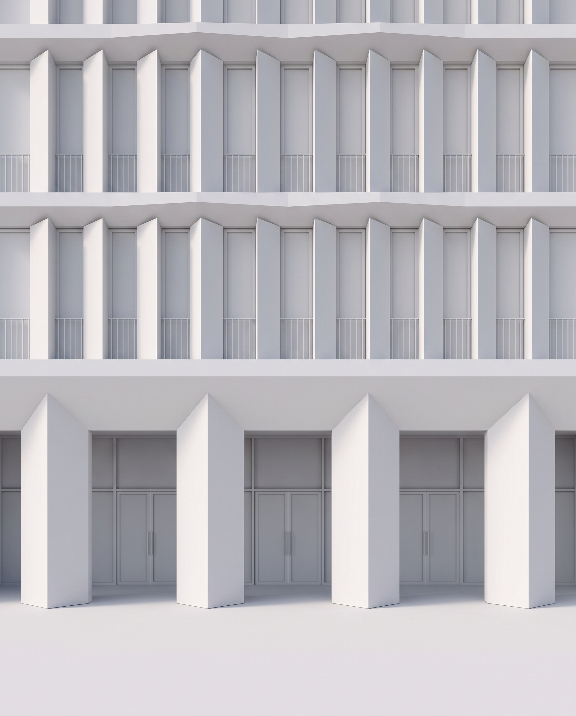
use the attached image as the primary and authoritative reference the existing image is already very close to the intended architecture this is a geometry study only preserve the existing camera crop overall proportions floor heights ground floor structure and fa ade rhythm do not redesign the architecture 1 camera and crop preserve exactly keep exactly the current camera position camera height viewing direction frontal perspective crop fa ade scale within the image floor heights overall proportions the image represents only a cropped portion of a much larger building the building continues beyond the left edge the right edge the top edge the image boundaries are camera crop boundaries not the boundaries of the building do not zoom out do not show the complete building do not introduce building corners do not show the roof do not change the viewpoint 2 ground floor preserve the current ground floor structural geometry is correct keep the existing ground floor columns exactly as they are they are large structural columns with a square cross section rotated 45 degrees in plan creating the existing diamond like expression in frontal view preserve exactly column dimensions square cross section 45 degree rotation spacing height position projection relationship with the horizontal structure above do not redesign the ground floor the ground floor glazing will be developed separately later so keep it simple and visually secondary for now 3 upper fa ade overall organisation preserve the existing repetitive upper floor fa ade system the upper levels consist of 1 repeated vertical projecting elements 2 recessed windows between them 3 continuous horizontal floor beams 4 small individual metal balustrades in front of the windows maintain the same floor to floor heights and the same repetitive fa ade rhythm all window bays must maintain the same clear width do not create narrower or wider windows 4 critical upper vertical element geometry all upper level vertical elements must be exactly identical in their physical geometry unlike the ground floor columns these upper vertical elements have a rectangular cross section every upper vertical element must use exactly the same rectangular cross section width thickness depth proportions height projection rotation angle surface dimensions one single vertical element geometry must be repeated throughout the fa ade do not create individual variations do not make some elements wider do not make some elements thinner do not make some deeper or shallower do not change their rotation angle individually do not taper them do not distort their rectangular cross section because the section is rectangular and rotated one visible face naturally appears narrower and the other visible face naturally appears wider this relationship must remain identical for every repeated element the apparent difference between the two visible faces must come only from the geometry and rotation of the same rectangular cross section 5 critical orientation by bay the geometry of every upper vertical element is identical the only variation is the direction in which the identical rectangular element is rotated follow the three bay directional organisation of the original sketch left bay the repeated vertical elements are oriented toward the right middle bay the repeated vertical elements are oriented toward the left right bay the repeated vertical elements are oriented toward the left therefore the directional sequence is right left left the left bay is effectively the mirrored orientation of the other two bays important mirroring the direction must not change width depth proportions rotation angle projection window width the right facing and left facing elements are mirrored versions of exactly the same rectangular profile within each bay every element must be perfectly parallel and identically rotated do not independently rotate individual columns maintain constant and identical clear window widths throughout the fa ade 6 critical horizontal beams the current horizontal beams need to be corrected to follow the original sketch they must not be simple straight beams they must also not become a sequence of semicircular arches scallops hanging curves or decorative concave shapes the horizontal beam remains a continuous horizontal architectural element its top edge remains completely straight and horizontal its geometry changes only on the lower surface between two consecutive upper vertical elements the underside of the horizontal beam must form one very smooth continuous and shallow curved transition the curvature should develop progressively across the full width of the window bay starting from the horizontal underside above the window the surface should transition gradually and continuously toward the projecting vertical element the curve must meet the vertical element naturally and tangentially the vertical element follows and completes this geometric transition think of the horizontal beam and vertical element as one continuous tectonic system rather than two independent objects the transition must be broad smooth gradual continuous shallow stretched across the bay integrated into the vertical element it must not be a short local curve a small rounded corner a semicircle a hanging u shape a deep scallop an arch a decorative moulding a repetitive ornamental wave the lowest part of the beam remains close to the window head from there the underside rises very gradually across the bay until it reaches the projecting vertical element at the vertical element the curved surface terminates in the sharp projecting edge created by the rotated rectangular profile the result should closely reproduce the geometry indicated in the original sketch a restrained continuous curved underside connecting each window bay to the projecting vertical elements repeat exactly the same curved geometry for every equivalent bay 7 windows and balustrades keep the windows tall narrow vertically proportioned recessed behind the projecting vertical elements all windows must have the same width and height maintain identical spacing between vertical elements keep the individual balustrades in front of each opening they should remain simple lightweight and geometrically secondary do not create continuous balconies 8 white model only this stage is only to resolve architecture and geometry render the entire architecture as a uniform matte white off white clay model all solid architectural elements must use the same neutral white material glazing may be represented only as simple neutral grey transparent surfaces so that openings remain readable no realistic materials no stone limestone travertine concrete texture brick timber metal finishes coloured frames material joints weathering reflections intended as realistic material effects 9 no environment do not add trees plants vegetation planters people furniture cars signage street furniture landscaping surrounding buildings decorative objects use only a plain neutral ground plane neutral soft daylight only final priority the objective is not to redesign the fa ade correct only the unresolved geometry while preserving the successful parts of the current image highest priorities 1 preserve the exact current camera and crop 2 preserve the successful ground floor column geometry 3 make all upper vertical elements geometrically identical 4 use the directional sequence right left left for the three bays 5 maintain exactly equal window widths 6 reconstruct the horizontal beam underside as the broad smooth and continuous curved transition shown in the original sketch 7 keep the top edge of every horizontal beam perfectly straight 8 maintain a pure white architectural model with no materials and no landscape