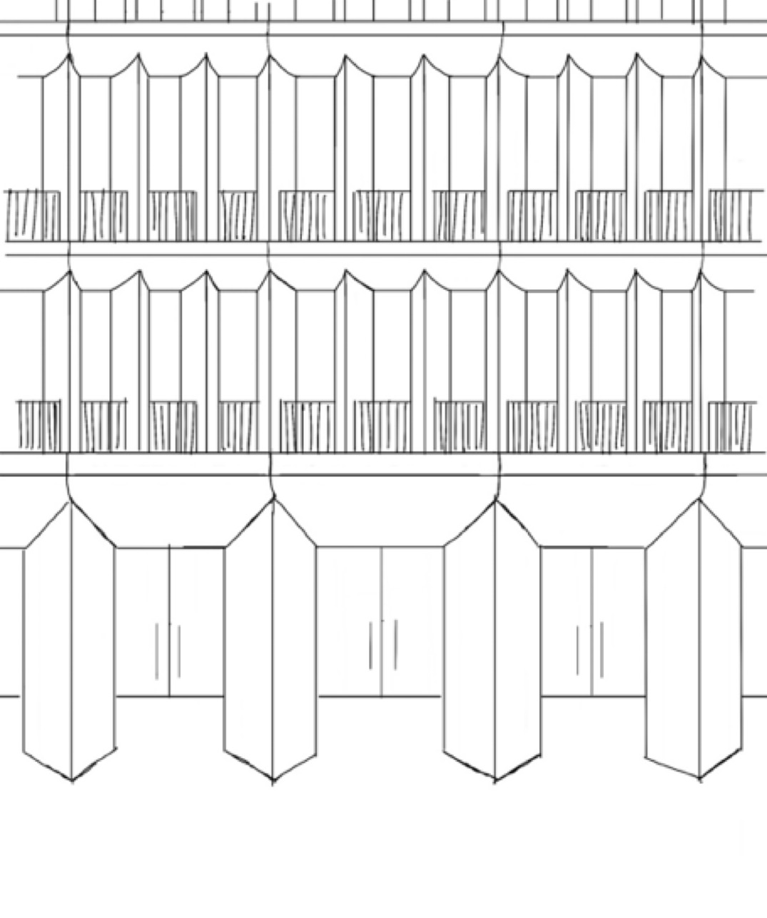
use the attached sketch as the primary and authoritative reference for the geometry create a clean white clay 3d model of exactly what is drawn do not redesign embellish or reinterpret the fa ade camera crop keep exactly the frontal viewpoint and crop of the sketch the sketch represents only a cropped portion of a much larger building the building continues beyond the left right and top edges of the image do not show building corners lateral terminations or the roof ground floor follow the ground floor geometry exactly as drawn the large ground floor columns are identical square sections rotated 45 degrees all ground floor columns must have exactly the same dimensions and rotation the ground floor glazing is located behind these columns recess the entire glazing plane clearly behind the columns creating a deep covered zone between the projecting columns and the glass keep the glazing as a simple continuous recessed plane upper vertical elements follow the vertical elements exactly as represented in the sketch they are rectangular sections rotated in plan not square sections create one identical vertical element and repeat it every vertical element must have exactly the same rectangular section width depth rotation projection proportions because of the rotation each element has a thinner visible face on the left and a wider visible face on the right repeat this geometry consistently all window bays must have exactly the same width ignore small inaccuracies in the hand drawing and regularize the spacing upper horizontal elements very important follow the profile drawn in the sketch literally do not create scallops arches hanging curves or decorative curved pieces there is only one horizontal element between each level the horizontal element has a very subtle smooth geometric deformation where it meets the projecting vertical elements starting from the straight horizontal upper edge of each window the surface gradually and smoothly rises toward the adjacent projecting vertical element this transition extends smoothly from the window edge toward the vertical element it must be extremely subtle the horizontal element must remain visually predominantly horizontal the vertical element meets and follows this smooth curvature do not create a deep u shaped curve do not create a semicircle do not create a hanging curved band do not create two horizontal layers do not create a curved element underneath a straight beam do not exaggerate the curvature look carefully at the original sketch and reproduce its line geometry as literally as possible special rotation follow the local change of orientation shown in the sketch there is one bay between the two large ground floor column alignments on the left where the upper rectangular elements rotate in the opposite direction use exactly the same rectangular section only reverse its rotation the window width must remain exactly the same white model only this is only a geometry study all solid architectural surfaces must be uniform matte white clay glazing simple neutral light grey transparent glass no realistic materials no stone no concrete texture no timber no metal finishes no colours no material joints no landscape no trees no vegetation no planters no people no furniture no cars no street context no surrounding buildings use a simple white ground plane and neutral soft studio daylight the purpose of the image is only to understand the geometry most important read the sketch literally do not invent architectural details that are not drawn do not exaggerate the curved horizontal geometry do not convert the horizontal elements into scallops keep all upper vertical elements identical keep all upper window bays equally spaced keep the ground floor glazing recessed behind the columns